PCB Rigid and Flexible PCB Factory will discuss with you what rigid-flexible PCBs are, the advantages of using them, and the rules for designing with them.
In electronics, we sometimes encounter new technologies that seem to have their origins in the past. Rigid-flex PCB technology dates back 50 years to when the wiring harnesses in spacecraft needed to be replaced. The first commercial mobile computer (weighing over 25 pounds!) used both rigid and flexible technology.
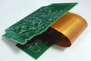
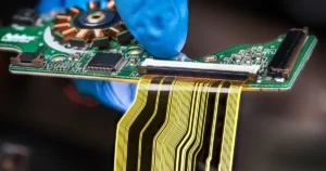
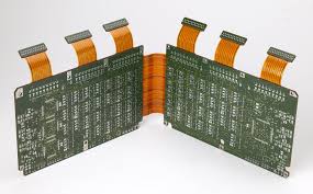
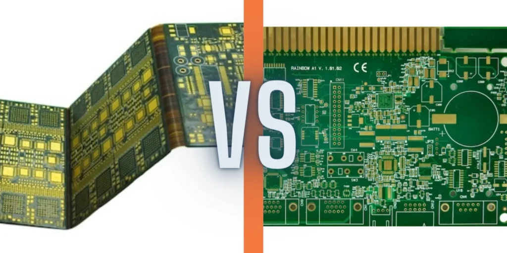
What is a rigid-flex PCB? uses a rigid-flex PCB and laminates a flexible circuit substrate and a rigid circuit substrate together. Rigid-flex PCBs span the boundaries of traditional rigid PCBs and the unique characteristics of flexible circuits. A conductive plating or rolled annealed copper conductor is photo-etched onto a flexible insulating film.
Flexible circuits include laminated thermal, acrylic adhesives as well as pressure from flexible polyimide and copper laminates.
What are the advantages of soft and rigid boards?
Rigid boards are still present in the manufacturing back panel. As with traditional PCBs, you can mount components on a rigid board. Because of the integration between rigid and flexible circuits, rigid-flex designs do not use connectors or connecting cables between parts. Instead, the flex circuitry electrically connects the system together.
The missing connectors and connecting cables operate as follows:
1, to improve circuit transmission without signal loss;
2. Adapt to control impedance;
3. Eliminate connection problems, such as cold junctions;
4. Reduce weight;
5. Make room for other components.
Each rigid-flexible PCB is divided into regions with different materials and different layers. The rigid area may have more layers than the flexible area, and the material moves from FR-4 to polyimide in the transition area. Complex designs often change from rigid to flexible and back to rigid. When these intersections occur, the overlap of rigid and flexible materials requires that the holes be kept away from the transition region to maintain integrity. In addition, many rigid-flex designs include stainless steel or aluminum stiffeners to provide additional support for connectors and components.
Flexible circuits always have bent wires that can interfere with wiring. Due to possible material stress, it is not possible to place components or vias near the bend line. Even with properly placed components, flex-flex circuits can cause repeated mechanical stresses on surface mount pads and vias. Your team can relieve these stresses by securing the pad with through-hole plating and supporting it with additional overlay support pads.
Electromechanical factors affecting both flexible circuits and rigid boards need to be considered when designing rigid-flexible boards. When building your design, pay attention to the ratio of bend radius to thickness. For flexible circuits, narrowing or increasing the thickness of the bend area increases the likelihood of failure. Manufacturers recommend keeping the bend radius at least ten times the thickness of the flexible circuit material.
Avoid bending the flex circuit along its exterior or compressing the flex circuit along its interior. Increasing the bend angle above 90° increases the tension on the flex circuit at one point and compresses it at another.
Another key issue for rigid flex reliability is the thickness and type of conductor in the flex region. You can reduce the thickness and mechanical stress by reducing the amount of plating on the conductor and using only pads. Using heavy copper, gold, or nickel plating can reduce flex flexibility and allow mechanical stress and fracture to occur.

