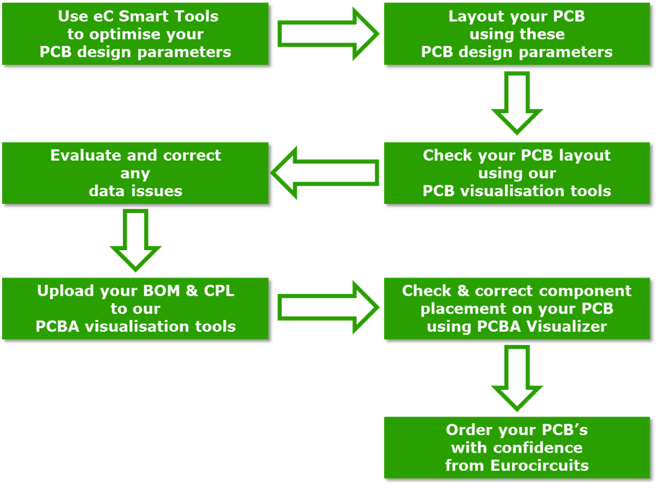
In the manufacturing industry, do designers need to check the design results after they have designed the PCB? The answer is yes, and there is more than one way to check.
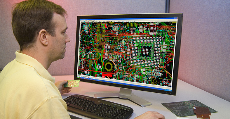
The first is the DRC check, also known as Design Rule Check, which is used in PCB design software (EDA) to check and discover designs that do not conform to a predetermined design specification in real-time during the PCB Layout process. Used to ensure the correctness of the design and meet the conventional design specifications as a starting point, is an indispensable part of the PCB design. Based on the role and purpose of the DRC, it typically has no more than 100 check details.
The second is DFM inspection, also known as Design for Manufacturability (DFM) analysis, which is a comprehensive design review of PCBs and PCBAs for manufacturability before manufacturing based on PCB design data simulated by real 3D component models and actual manufacturing processes, to discover design flaws or deficiencies, process difficulties, manufacturing risks, design and process mismatches, etc. in the first place, ensuring The design and process capabilities are perfectly matched, materially reducing the number of product trials, saving production costs, and improving product reliability.
These two checks are different checks at different stages of the design, and one cannot be used without the other.DRC is a specification (constraint) used by PCB design software to ensure that its own design is not violated.Meeting the DRC check is the most basic requirement for PCB design, and meeting the DRC does not necessarily mean that the manufacturability requirements are met.DFM is the bridge between PCB design and manufacturing process, and belongs to the category of process design. It allows you to discover mismatches between design and manufacturing processes, assess manufacturing difficulties, manufacturing risks, etc., which are not covered by DRC in PCB design software.
There is no conflict between DFM per se and DRC inspection; the two solve different problems, have different phases, and have different end goals. So the difference is also very clear.
1. The difference between DRC and DFM
2. Metaparametric library differences
3. DFM component library = 3D physical model
4. DFM: PCB + component model + process = assembly simulation
5. DFM: Realistic 3D Simulation Assembly Simulation Analysis
6. DFM: comprehensive analysis rules
Therefore, post PCB design inspection should be performed at different stages to ensure that the product meets the expected results.
