In the electronic assembly industry, SMT and DIP are two important electronic component installation methods, each with unique characteristics and application scenarios. When choosing which technology to use, it is necessary to comprehensively consider factors such as specific application requirements, production costs, and production efficiency.

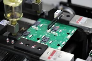
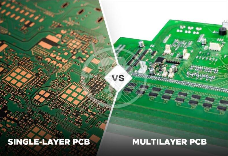
SMT, also known as surface mount technology, connects circuits by directly installing surface mount components (SMC/SMD) such as chips, resistors, capacitors, and diodes on the surface of printed circuit boards without pins or short leads. Accurately solder onto the surface of PCB using methods such as surface mount machine and reflow soldering. The advantages of SMT technology are compact structure, small size, vibration resistance, impact resistance, good high-frequency characteristics, and high production efficiency. Due to the compact size of electronic components, PCB design can achieve higher space utilization and also facilitate automated production, reducing production costs.

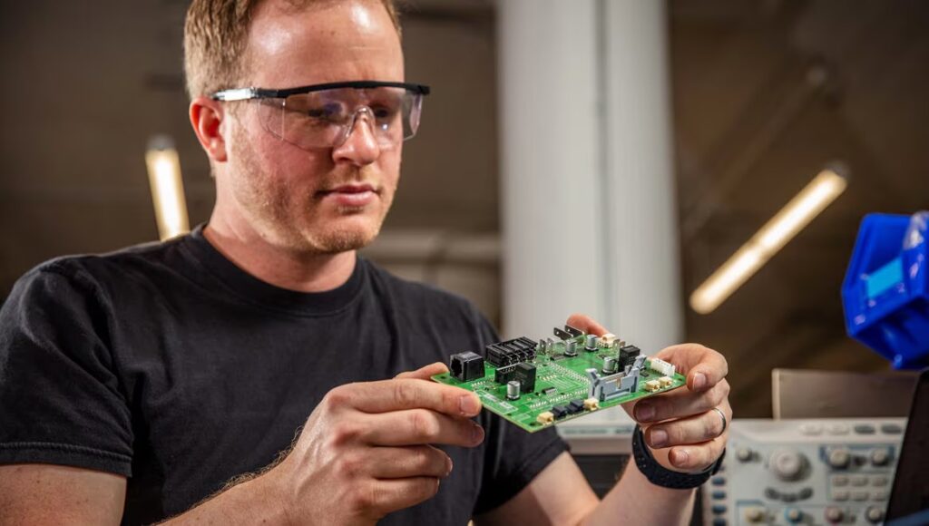
DIP technology uses dual row direct insertion components, which have pins that can be installed on the PCB through plug-in methods, and then connected to the PCB through wave soldering or manual soldering of the pins. The characteristics of DIP technology are that the pin based electronic components have a large volume, strong anti vibration ability, and high stability. However, due to the need for manual insertion and soldering, the automation level of DIP technology is relatively low, and production efficiency is also relatively low. In addition, DIP components occupy a large space, which is not conducive to achieving miniaturization and lightweighting of electronic products.
In terms of application, SMT and DIP technologies have their own advantages and disadvantages. SMT technology is widely used in consumer electronics, communication equipment, computer hardware and other fields due to its high degree of automation and high production efficiency. DIP technology, on the other hand, has advantages in application scenarios that require significant mechanical stress and vibration, such as automotive electronics and industrial control, due to its strong anti vibration ability and stability.
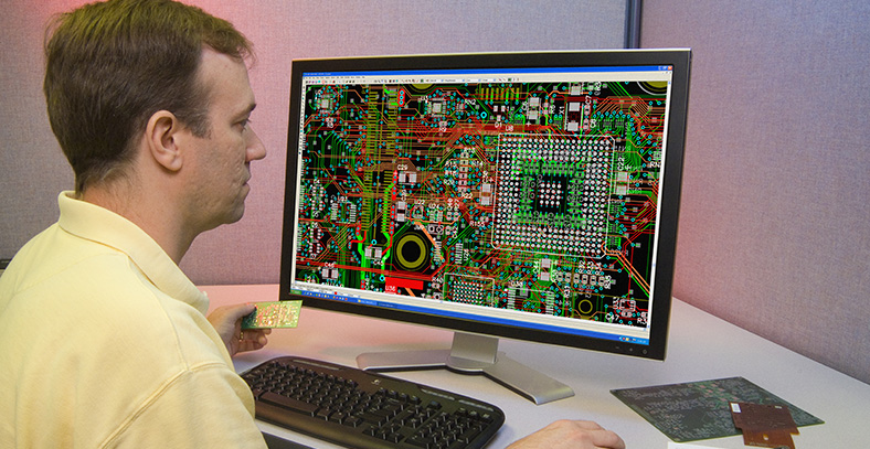
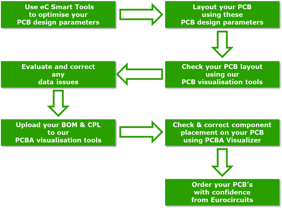
In addition, there are differences between SMT and DIP in PCB design. The layout of SMT components needs to consider the packaging, arrangement, and spacing of the components to ensure soldering quality and circuit stability. The layout of DIP components needs to consider the socket position and arrangement of plug-in components to ensure that the components can be correctly inserted and soldered onto the PCB. These design differences require different processes and equipment for SMT and DIP in the PCB manufacturing process.
