The circuits that are assembled on perfboard and stripboard are considered less impact-resistant than the printed circuit board assembly; however, it is not categorized as fragile. Perfboard and stripboard are basically different from each other, but it is both a material that is being used for prototyping electronic circuits.
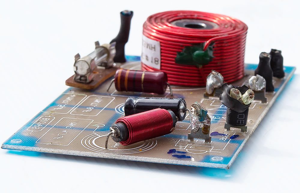
Perfboard is a thin, rigid sheet that have pre-drilled interval holes across in the square grid of about 0.1 inches (2.54 micrometers) or 2.54 mm spacing. A round or square copper pad usually ringed these holes. This 0.1 or 2.54 mm spacing in the grid system is to accommodate the integrated circuits in the DIP-packages.
If you don’t want to stash a huge amount for an expensive perfboard, you may then opt to have a pad only on one side of the board, which is less expensive than having pads on both sides or a plate-through holes. The builder will connect the pads, which are electrically isolated, with the use of a wire wrap or a point-to-point wiring technique. Resistors, integrated circuits, and as well as capacitors are being soldered in the prototype boards. A substrate is either made of a fiberglass that’s been reinforced by epoxy laminate or paper that’s been laminated with a phenolic resin.
Before you can truly proceed in building a circuit board assembly in the perfboard, the builder will plan in detail the locations of the components and their connections through the use of a software tools. Software that is being used for PCB layout can also be used to generate the perfboard layout.
The builder will have the components’ position so that all the leads will fall in an intersection of 0.1 inches (2.54 micrometers) or 2.54 mm grid. More than two copper layers are being used in routing the connections.
Having multiple overlaps may not be considered a problem for insulated wires. Kynar or Tefzel, which are thin solid core wires with temperature-resistant insulation, is being preferred for insulated wires. It has a wire gauge which is about 24-30 AWG. The wire is simply being inserted and pulled loose, thereby having a clean, stripped end. Developing wiring circuits can be done through the use of the wire wrap technique or point-to-point wiring. You may also opt to use bare copper wire to merge a number of connections to create an electrical bus such as the circuit’s ground. It is a better method than having a wiring that has rats-nest style.
There are two schools of thought pertaining to the number of wirings, one of which fosters the idea that achieving many connections is possible even without adding an extra wire. This may be possible by bending any existing leads on capacitors, resistors, and the like into the position and soldering the leads in order to achieve the desired electrical connections. The second school of thought have an entirely different angle of looking at things, for it rejects the bending of excessive leads of components to be used for wiring. It adheres to the idea that removing a component may lead to a certain difficulty, especially when a repair is being needed.
Whatever school of thought that is adapted, it always boils down to the expertise of the builder. You may opt to consider Fast Turn PCB a leading company in the circuit board assembly industry. A length of 12 years of experience in the industry had made them a company to be relied on in the PCB industry. Fast Turn PCB is a PCB, and circuit board assembly manufacturer had already earned its mark of excellence in delivering quality products and services.
