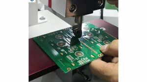
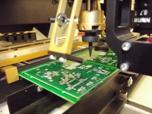
With the increase in the quality of electronic assembly technology and the competitive needs of the market, fully automatic inserters are rapidly gaining popularity. This has led to increasing demands on the quality of punching of single-sided PCB paper-based boards (a few single- and double-sided non-metallized hole epoxy-glass cloth substrates also use punching).
This article introduces the top ten common defects and solutions for PCB punching, which are burrs, bulging around the copper foil face aperture, copper berries turning upward at the aperture, layered white around the substrate face aperture, tilted and off-set hole walls, rough section, cracks between the hole and the hole, bulging shape, jumping on the waste and clogging the waste, etc., specifically follow the club technology PCB engineers to learn more.
I. Burrs
Cause:
The gap between the concave and convex die is too small, resulting in cracks on both sides of the convex and concave dies that do not overlap, and two extrusion shears occur at both ends of the section.
The gap between the concave and convex die is too large, and when the convex die is lowered, the crack occurs late and completes the shear like a tear, causing the crack to not overlap.
The edge is worn or rounded and chamfered, the edge does not act as a wedge split, and irregular tearing is produced throughout the section.
Solution:
Rational selection of punching clearance for concave and convex dies. Such punching and shearing is between extrusion and stretching, and when the convex die cuts into the material, a wedge forms at the edge, creating a nearly linear overlapping crack in the sheet.
Timely reconditioning of rounded or chamfered edges produced by concave and convex die edges.
Ensure vertical concentricity of concave and convex dies for uniform mating gap.
Ensure that the mold is mounted vertically and smoothly.
II. Bump around the copper foil face orifice
Cause of generation:
The gap between concave and convex die punching is too small, and the convex die edge is blunt. When the convex die enters the preheated and softened printed board, the board moves outward and upward around the convex die.
The convex die has a taper at the edge end. As the die continues to enter the sheet, the bulge around the hole increases as the die taper increases.
Solution:
The punched cut should exceed twenty percent of the original design thickness; otherwise replace the plate or redesign the die.
Punching should have sufficient press force to overcome the back squeeze of material movement during punching;
III. The orifice copper berth is turned upward
Cause:
Due to backlash, the copper foil is pulled into the blanking gap between the concave and convex dies.
The copper foil is poorly bonded to the substrate, and when the die is pulled out of the punched printed board hole, the copper foil is lifted upward with the die.
The convex die has a chamfered cone at the edge end and bulges and deforms so that the copper foil is lifted upward with the convex die as it is pulled out of the hole in the printed board being punched.
Solution:
Use positive punch.
Replacement of the convex die.
The mating gap between the convex die and the unloading plate should not be large, and a slip fit should be used.
Translated with www.DeepL.com/Translator (free version)
Four, layered whitening around the substrate’s face orifice
Cause:
Improper concave and convex die punching clearance or blunt concave mode edge. When punching, it is difficult for the punched plate to form shear cracks at the concave mode edge.
Poor substrate blanking performance or failure to preheat before blanking.
Low pressure material force.
The lower leakage hole of the concave die edge is clogged or has a high resistance to leakage, resulting in expansion delamination.
Solution:
Reasonable widening of concave and convex die blanking clearance;
Timely repair of blunted concave die edges;
Increase press force;
Adjust the substrate preheat temperature;
Expand or ream the leaky holes
Translated with www.DeepL.com/Translator (free version)
V. Hole wall tilt and deflection
Causes:
Poor rigidity of the convex die, unstable centering, and tilted punching into the workpiece.
The convex die is installed at an inclined angle or the fit clearance with the unloading plate is too large, and the unloading plate does not play a precision guiding role for the convex die;
The mating gap between the concave and convex dies is not uniform. On the side with a small gap, the convex die is subjected to a large radial force and slips towards the side with a large gap;
Poor concentricity of concave and convex die assembly; off-set shape of push plate and concave and convex die; too poor precision of push plate and concave die fit (when referring to compound punching).
Solution:
Rational selection of the material of the convex die; improve the rigidity, strength, hardness and unstraightness of the convex die.
Improve the machining concentricity and assembly concentricity of the convex and concave dies.
Improve the mating accuracy of the cam die and unloading plate to ensure precision guidance.
Ensure the machining accuracy and assembly accuracy of guide pillar and guide bush; reduce the mating gap between the profile of push plate and concave die, and make the profile of push plate and concave and convex profile consistent.
VI. Rough section
Cause:
Concave and convex die blanking clearance is too large; the concave die edge is severely worn.
The punching force of the press is insufficient and unstable.
Poor sheet blanking performance. For example, high glue content in the substrate, substrate, aging, low lamination bonding, etc.
Solution:
Select the proper die blanking clearance for concave and convex dies.
Timely trimming of concave die edges.
Choose a substrate with good punching performance and control the preheating temperature and time strictly according to the process requirements.
Translated with www.DeepL.com/Translator (free version)
VII. Holes of holes and inter-cracks
Causes:
The hole wall is too thin and the radial extrusion force during punching exceeds the hole wall strength of the printed board substrate.
Two holes very close to each other are not punched out at the same time, and the later punched hole is cracked when the convex die enters the sheet because the hole wall is too thin.
Solution:
The hole spacing on the printed board should be reasonably designed, and the hole wall should not be smaller than the thickness of the substrate.
Holes that are close to each other should be punched out simultaneously with one die.
Two convex dies in close proximity are made with different lengths that differ by 0.5mm, so that the more concentrated punching forces in a small area are instantaneously dispersed.
VIII. shape bulge
Causes:
Improper mold design. For the large size of the printed board, such as the use of concave die without pushing the plate of the drop material, the stamped printed board in the case of self-weight, always to the concave mode hole bending. In addition, the convex die down punch, airflow to the workpiece has a shock wave, so that the center of the workpiece more downward curvature, and near the concave die edge downward bending amount is very small, resulting in the shape of bulging.
Deformation of the concave die for profile dropouts, with bulging at the long edges.
Solution:
When the profile size of the printed board is larger than 200mm, it is advisable to punch the profile using a die with an up-and-down structure. If the die structure of the drop material is used, a push plate with elastic resting force must be installed in the concave die so that the printed plate is not deformed.
Increase the wall thickness of the concave die or choose a material with sufficient flexural and tensile strength to build the die.
Minimize heat treatment deformation of concave dies. For concave dies with complex geometry, selective heat treatment hardening followed by wire cutting can be used to overcome the distortion.
9. Jump on waste
Sometimes part of the scrap does not fall down when punching, but jumps up; some enter the workpiece hole and need to be removed manually; some jump on top of the lower die, affecting the normal operation of punching.
Cause of generation:
The copper foil has poor adhesion to the base material, and the copper foil on the scrap tends to come off during punching and enter the punched hole as the die exits the concave die.
The concave die gap is too large and the leakage is not smooth, so when the convex die exits the concave die to unload the material, the scrap jumps up with it.
The concave die hole has an inverted cone, and the punched scrap is difficult to drop, but instead jumps upward as the die exits the concave die.
Solution:
Enhance incoming inspection of substrate materials.
Reducing the gap between the concave and convex die and enlarging the leakage hole.
Timely trimming of the chamfer in the concave die hole.
X. Waste clogging
Cause:
Die edge too high, too much scrap accumulation.
Concave mold leakage hole is too small or has a chamfered cone at the edge and the hole wall is too rough.
The concentricity of the leakage holes on the lower gasket and lower die holder and the concave die holes are poor, and the holes are aligned with like steps.
With too large a leak hole, the waste tends to make irregular piles in the hole; it also tends to clog when two adjacent leak holes are cut internally.
No guide hole on the lower gasket, when the scrap falls from the concave die hole, it can’t enter the leakage hole below smoothly.
Solution:
Lowering the die edge between 0.2mm will reduce the number of scrap build-ups.
When the concave die hole is less than ф0.2mm, it is better to make a tapered hole for the leakage hole, and when the concave die hole is larger than ф0.2mm, the leakage hole can be made into a straight hole, and the height part of the concave die edge should not have an inverted taper.
Adjust the vertical concentricity of the leakage holes on the concave die, the lower gasket, and the lower die holder, and enlarge the leakage holes on each part.
When two adjacent leakage holes are cut inside, they should be made into a waist round hole in order not to block the leakage, or into one large hole.
The de-bracing bars of the concave die support bar and the lower die seat should have sufficient slope or leakage channels to allow the scrap to leak down smoothly without accumulation and blockage.

