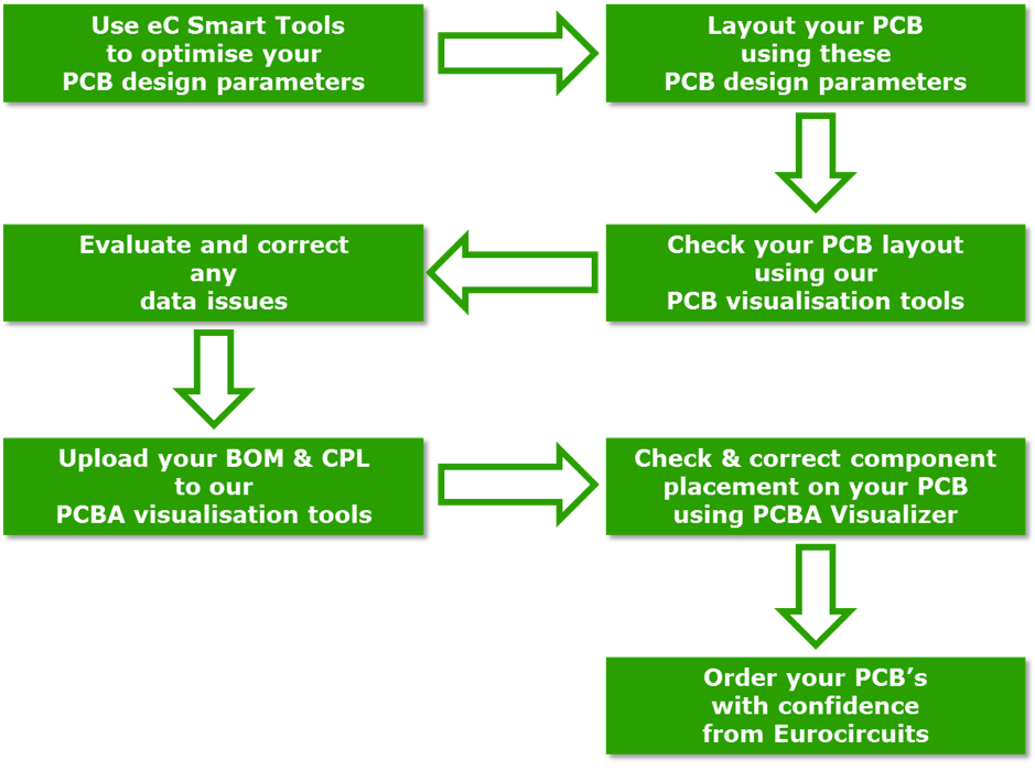
In the process of producing PCB boards, a series of documents are required to ensure the accuracy and efficiency of manufacturing. These documents cover every step from design to manufacturing, providing clear guidance and reference for manufacturers. The following are the main file formats required for producing PCB boards:
1. Gerber file:
The Gerber file is a standard file format for PCB design, which contains layer information of the PCB, such as pads, pad discontinuation, wiring, sockets, etc. These documents are crucial for manufacturers as they provide all the geometric information required to manufacture PCB boards.
2. Assembly drawings:
The assembly drawings provide additional information, including all special instructions such as component placement details, reference numbers, orientation, and precautions for assembly technicians.
3. Drilling files:
Drilling files (usually generated in Excellon format or ASCII file) provide PCB drilling coordinates and size information, specifying the hole size of components, through holes, and mounting holes.
4. PCB design files:
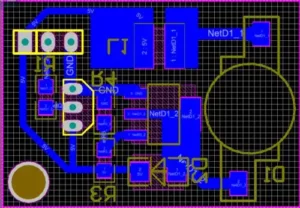
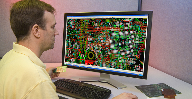
This includes circuit schematics, packaging libraries, PCB layout diagrams, network tables, etc. The circuit schematic is the starting point of design, and the packaging library contains the packaging information of the components. The PCB layout diagram displays the layout of the components on the circuit board, while the network table describes the connection information between the components.
5. BOM (Bill of Materials):
The BOM lists all the components required for PCB design, such as chips, capacitors, resistors, connectors, etc. This helps the manufacturing plant to procure the required components and ensure that all components are correctly placed on the PCB.
6. Detection file:
Such as AOI testing files, X-ray testing files, ICT testing files, etc., these files are used to test the quality and performance of circuit boards.
7. Manufacturing drawings:
This is an engineering drawing that includes board dimensions, drilling dimensions, layer stacking, tolerances, surface treatment, and other manufacturing related details. Manufacturing drawings are important references for PCB manufacturers during the production process.
8. Center coordinate file:
Also known as picking and placing files, it provides coordinate and directional information for each component on the PCB. This is crucial for the automatic assembly process, guiding the placement of components on the PCB.
In addition, depending on the PCB design software used, other specific formats of files may also be generated, such as brd files (Cadence Allegro, Eagle), max files (Cadence ORCAD), pcbdoc files (Altium Designer), etc. These files are generated by the corresponding software during the design process, used to save and transfer design data.
The file formats required for producing PCB boards are diverse, and each file plays an indispensable role in the production process. The accuracy and completeness of these documents are crucial for ensuring the quality and performance of the PCB board.
