SMT sample manufacturing is a complex and precise process that requires customers to provide comprehensive and accurate design and production data. From basic design files (such as Gerber files and BOM files) to location and coordinate files, to process and testing files, every detail is crucial. Through effective communication and close cooperation between both parties, the smooth progress of SMT sampling process can be ensured, and ultimately high-quality products can be obtained.
1、 Basic design documents
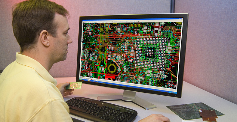
Gerber file is one of the basic materials for SMT sampling, which is a graphic data file exported from PCB (printed circuit board) design files. This document must include the following key layers:
Pad layer: defines the position and shape of all solder joints.
Solder mask: Indicates which areas should not be covered by solder to prevent short circuits.
Screen printing layer: It contains screen printing information on the circuit board, such as component identification, product model, version number, etc.
Steel mesh layer: used to guide the production of SMT steel mesh and ensure the accuracy of solder paste printing.
In some cases, if there is concern about the leakage of Gerber files, the files can be processed by retaining only the parts required by the factory and signing a confidentiality agreement.
The BOM file (Bill of Materials) is a detailed description list of materials that corresponds to the actual materials. It contains the models, specifications, and quantities of all components on the circuit board, and is a standard document for factory incoming inspection and production procedures.
2、 Location and Coordinate Files
The coordinate file describes the position information of the components on the PCB board. This file is usually provided in. txt or Excel format, with metric units (default uses mm), and includes the PCB board origin, which is usually designed in the lower left corner.
The layout diagram is a specific part of a PCB file exported from R&D software, mainly including solder pads and silk screen layers, used by factories to verify whether the SMT material placement position is correct.
3、 Process and testing documents
The process requirements document provides a detailed list of special requirements and precautions during the manufacturing process, such as welding temperature, welding time, cleaning treatment, etc.
If functional testing or ICT (online testing) of the circuit board is required, the customer needs to provide relevant testing documents and procedures. The testing documents should clearly define the testing steps, testing points, and expected results to ensure that the manufacturer can accurately conduct testing and evaluate the quality of the circuit board.
4、 Other auxiliary files
If the customer’s board is designed as a splicing board, a splicing file is also required. The splicing file describes how to splice multiple small boards into one large board for production, in order to improve production efficiency and reduce costs.
According to specific requirements, customers may also need to provide other related documents, such as 3D model files, assembly drawings, user manuals, etc.
