PCB Prototype
PCB Prototype involves transforming electronic design from concept to actual physical circuit boards for testing, validation, and assembly of prototypes.
This process not only requires high precision and reliability, but also emphasizes fast response and cost-effectiveness to meet the requirements of rapid iteration in the product development cycle.
From simple single panels to complex multilayer boards, from conventional FR-4 substrates to high-performance high-frequency, high thermal conductivity materials, we can provide a diverse range of choices to meet the needs of various application scenarios.
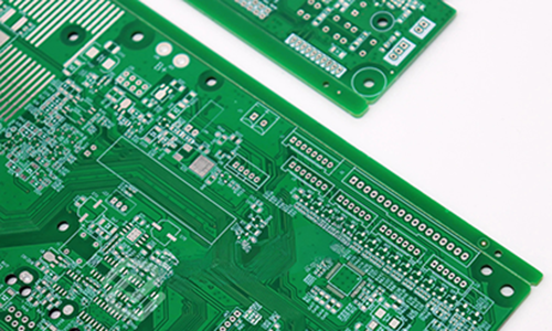
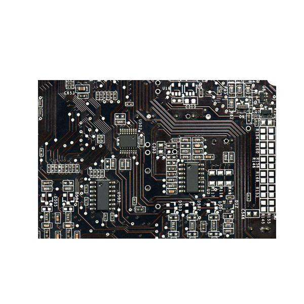
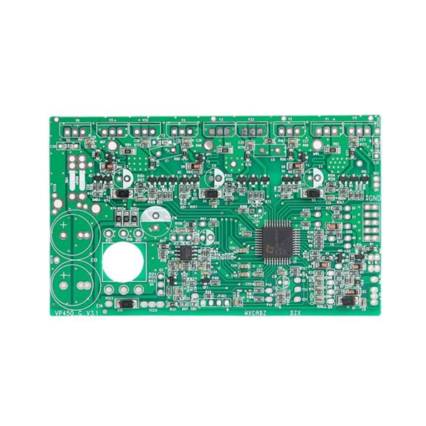
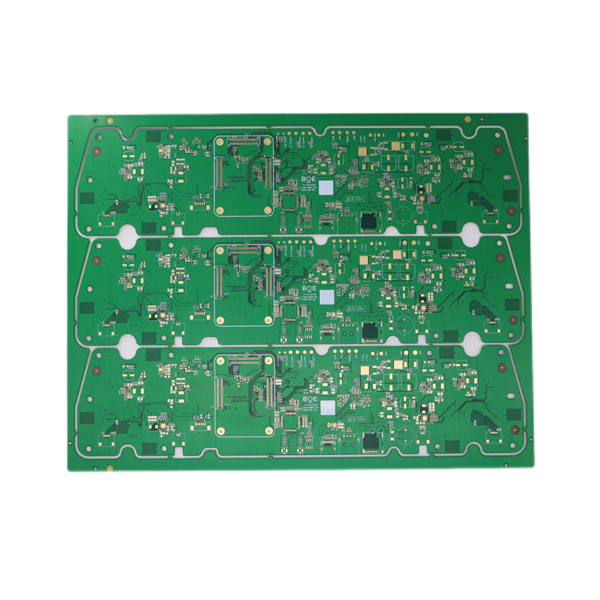
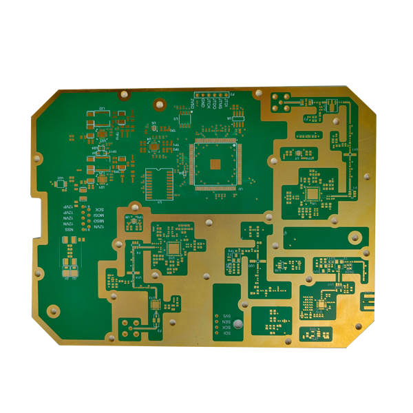
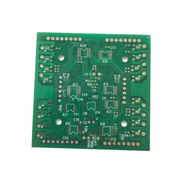
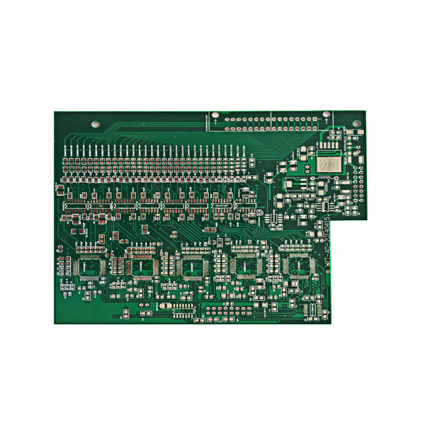
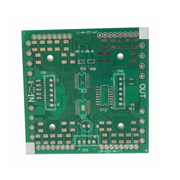
Product Showcase
Capabilities
| Capability | Parameter |
|---|---|
| Layer | Up to 50 Layers |
| Max Size | 600 x 500mm |
| Thickness | 0.2-7.0mm |
| Copper Thickness | 0.33-12 0Z |
| Min Line Width/Spacing | 2.5mil/2.5mil |
| Min Drill Hole | 6mil |
| HoleMin Hole To Line | 5mil |
| Impedance Tolerance | +10% or +5% |
| Dimension Tolerance | ±0.1mm |
| Material |
Shengyi S1000-2, S1141, ITEQ IT180A, Aluminum-Based & Copperbased, Rogers4350B,4003C,3003, RT5880,RT6010,TMM10/10iVT901, DuPont PI, ISOLA FR408HR, 370HR, TU872LK, Megtron 4, Megtron 6 etc. |
| Coverlay Opening Size | ≥0.6mm x 0.6mm |
| Surface Treatment |
ENIG ENEPIG I-Ag OSP HAL/HAL Lead Free Flash Gold Hard Gold |
Are you looking for a high-quality and full-range PCB fabrication, PCB assembly?
FAQ
The manufacturing time of PCB prototypes varies due to various factors, including the complexity of the circuit board, the manufacturing plant's production capacity, and order volume.
Generally speaking, simple single or double-sided board prototypes can be manufactured in a few days, while complex multi-layer boards or circuit boards containing special processes such as blind holes and buried holes may require longer time.
To shorten the manufacturing cycle, it is recommended to choose PCB manufacturers with advanced manufacturing equipment and efficient production processes.
Poor circuit: such as open circuit, short circuit, circuit width or spacing not meeting design requirements, etc.
Pad issues: Pad detachment, incorrect pad size, mismatch between pad and component pins, etc.
Drilling problems: aperture deviation, incorrect hole position, poor hole wall quality, etc.
Surface treatment defects: such as uneven coating of solder mask, blurry character printing, insufficient coating thickness, etc.
These issues may be caused by design errors, improper process control during manufacturing, or material quality problems.
Therefore, a detailed design review should be conducted before manufacturing, reliable manufacturers should be selected, and strict quality control should be implemented during the manufacturing process.
Manufacturing capability: Does the manufacturer have advanced manufacturing equipment and processes to meet your design requirements and production capacity needs.
Quality control: Whether the manufacturer has established a sound quality management system and can provide reliable quality assurance and after-sales service.
Price and delivery time: Compare the prices and delivery times of different manufacturers and choose the manufacturer with high cost-effectiveness.
Technical support: Does the manufacturer provide technical support and solutions, and can they assist in solving problems during the design or manufacturing process.
Electrical performance: The dielectric constant, dielectric loss, resistivity, and other electrical properties of the material should meet the design requirements.
Mechanical strength: The mechanical properties such as bending strength and impact strength of the material should be sufficient to ensure the reliability and durability of the circuit board.
Thermal stability: The material should have good thermal stability and be able to withstand certain temperature changes without deformation or cracking.
Processing performance: The material should be easy to process, such as drilling, etching, electroplating, and other processes should be able to proceed smoothly.
Cost: While ensuring performance, the cost of materials should be considered and materials with high cost-effectiveness should be selected.
Electrical testing: Check the conductivity, insulation resistance, withstand voltage and other electrical performance of the circuit.
Functional testing: Verify whether the circuit board works according to design requirements, including signal transmission, power distribution, and other functions.
Reliability testing: such as thermal cycling testing, wet heat testing, vibration testing, etc., to evaluate the reliability of circuit boards during long-term use.
Appearance inspection: Check the appearance quality of the circuit board, such as solder joint quality, solder mask coating, character printing clarity, etc